
Mastering the One Cylindrical One Ball Bearing Configuration in Motors
Introduction
Ever wondered why some motors use a specific bearing setup with one cylindrical roller bearing and one deep groove ball bearing? Known as the “one cylindrical one ball bearing” structure, this configuration is a popular choice in motor design for managing specific load conditions. It’s a strategic setup that balances axial and radial load handling while ensuring precise shaft positioning.
In this article, we’ll dive into what this configuration is, how it works, when to use it, and the critical considerations to avoid common pitfalls.
What is the One Cylindrical One Ball Structure?
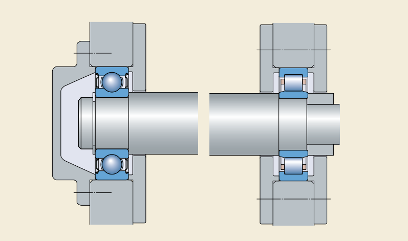
The “one cylindrical one ball” configuration is a motor bearing arrangement that combines one deep groove ball bearing with one cylindrical roller bearing (typically NU or N series). Here’s the breakdown:
-
Deep Groove Ball Bearing: Acts as the locating bearing, typically placed at the non-drive end. It handles axial (thrust) loads and keeps the shaft positioned.
-
Cylindrical Roller Bearing: Serves as the non-locating bearing, usually at the drive end. It excels at managing heavy radial loads but lacks significant axial load capacity due to its design.
In this setup, the ball bearing fixes the shaft axially and shares radial load support, while the roller bearing takes on the bulk of the radial load and allows axial movement within itself to accommodate thermal expansion. It’s like a tag team: the ball bearing ensures stability, and the roller bearing provides strength.
How Does the One Cylindrical One Ball Structure Work?
In a motor, bearings stabilize the shaft during rotation. The “one cylindrical one ball” configuration splits the workload efficiently:
-
Locating End (Ball Bearing): Anchors the shaft axially and supports some radial load.
-
Non-Locating End (Roller Bearing): Bears the primary radial load, with its internal axial float handling shaft expansion.
This setup shines in motors where radial loads peak at the drive end—like in belt-driven systems—while the ball bearing manages axial forces, such as the rotor’s weight or minor thrusts.
When Should You Use This Configuration?
Choosing the right bearing setup hinges on your motor’s load conditions. Here’s when the “one cylindrical one ball” structure is a smart pick:
-
High Radial Loads at the Drive End: Think belt pulleys or impellers. The roller bearing’s robust radial capacity handles these stresses effortlessly.
-
Moderate Axial Loads: The ball bearing can manage typical axial forces. For heavy axial loads, alternatives like angular contact bearings might be better.
But it’s not always the right fit. Avoid it when:
-
Radial Loads Are Low: In direct-coupled motors with minimal radial load, a dual ball bearing setup is simpler and more cost-effective.
-
Vertical Motors with No Radial Load: Here, the roller bearing might lack sufficient load, leading to issues like slippage.
Key Considerations for Using the One Cylindrical One Ball Bearing Structure
This configuration is powerful but demands attention to detail. Here’s what you need to know:
Minimum Load Requirements
Both bearings need a baseline load to function properly:
-
Roller Bearing: Requires a minimum radial load to prevent roller slippage, which can cause overheating or noise. A case study showed a motor’s roller bearing (NU 217) failing due to a 948 N load falling short of its 1.52 kN minimum, resulting in slippage marks on the inner race.
-
Ball Bearing: Also needs a minimum radial load. If the rotor’s weight and external loads balance out, the ball bearing might become unloaded, leading to overheating.
Pro Tip: Calculate actual loads. If they’re too light, opt for dual ball bearings.
Strategic Placement
-
Drive End: Position the roller bearing here for heavy radial loads.
-
Non-Drive End: Place the ball bearing here for axial positioning and lighter radial support.
This maximizes each bearing’s strengths.
Axial Fixation
-
Roller Bearing: Must be externally clamped to prevent movement, despite its internal axial float.
-
Ball Bearing: Fixed axially to secure the shaft.
Skipping this step risks shaft drift and wear.
Vertical Motor Challenges
In vertical setups:
-
The rotor’s weight becomes an axial load on the ball bearing.
-
Without radial load (e.g., direct coupling), the roller bearing may overheat due to insufficient load.
For such cases, reconsider this configuration.
Bearing Selection
-
Roller Bearing: Size it for the drive end’s radial load.
-
Ball Bearing: Can be smaller, as it mainly handles axial positioning and lighter radial loads. For significant axial loads, consider angular contact bearings.
Common Pitfalls and How to Avoid Them
Even a great setup can fail if misapplied. Watch out for:
-
Roller Bearing Slippage: Insufficient radial load causes overheating. Verify the load meets the minimum requirement.
-
Unloaded Ball Bearing: Balanced forces can leave it without radial load, leading to wear. Ensure proper load distribution.
-
Installation Errors: Unsecured bearings cause shaft movement. Double-check axial fixation.
Wrapping Up: Is This Configuration Right for Your Motor?
The “one cylindrical one ball” bearing configuration excels in motors with high radial loads at the drive end and moderate axial demands. But it’s not foolproof—success depends on load assessment. Before choosing it, ask:
-
Does the drive end face significant radial load?
-
Can the ball bearing handle the axial forces?
-
Will both bearings get their minimum loads?
If yes, you’re set. If no, a dual ball bearing setup might be smarter. Carefully matching bearings to loads ensures your motor runs smoothly and lasts longer.