
Bearing Fits Guide (H7/m6) & Free Tolerance Calculator (2026 Update)
Direct answer: H7/m6 is commonly used when the bearing inner ring rotates with the shaft and needs a firm shaft fit, while the outer ring is stationary in the housing. In this combination, m6 helps reduce inner-ring creep on the shaft, and H7 usually provides a practical housing bore fit. However, H7/m6 is not universal. Rotating housings, heavy shock loads, high temperature, aluminum housings, or precision spindle applications may require a different fit.
Introduction
H7/m6 is one of the most searched bearing-fit combinations because it connects two different tolerance decisions: H7 for the housing bore and m6 for the shaft. H7 does not describe the shaft, and m6 does not describe the housing. The correct fit depends on which bearing ring rotates, how the load acts, the bearing type, internal clearance, temperature, housing material, and assembly method.
This guide explains what H7 and m6 mean in a bearing fit, when the H7/m6 combination is commonly used, and when a looser or tighter fit may be required.
H7/m6 Fit: When H7 Housing and m6 Shaft Tolerance Are Suitable
The H7/m6 bearing fit is often used as a starting point for general rotating-shaft applications such as electric motors, pumps, fans, gearboxes, and similar industrial equipment. In these cases, the shaft rotates with the bearing inner ring, so the m6 shaft tolerance can help secure the inner ring and reduce creep. The H7 housing tolerance is usually considered when the outer ring remains stationary and easier assembly or axial location control is needed.
Before using H7/m6, confirm the rotating ring, load direction, shaft diameter, housing bore, bearing internal clearance, speed, operating temperature, housing material, lubrication method, and mounting process. If the application has shock load, vibration, thermal expansion, or evidence of fretting, H7/m6 should be checked against a tighter or looser fit recommendation rather than used automatically.
If VFD current or electrical erosion is present, report it separately. H7/m6 fit selection does not solve electrical bearing damage; the application may require an insulated bearing or grounding solution.
| Application condition | Rotating ring | Shaft fit direction | Housing fit direction | Why H7/m6 may work | Risk if too loose | Risk if too tight |
|---|---|---|---|---|---|---|
| Standard motor, pump, fan | Inner ring rotates | m6 or similar interference fit may be used | H7 often used for stationary housing | Helps secure inner ring while allowing practical housing assembly | Inner-ring creep, fretting, vibration | Reduced internal clearance, heat |
| Gearbox fixed bearing side | Usually inner ring rotates | Fit must secure rotating ring | Housing fit depends on load and location method | H7/m6 may suit moderate loads | Seat wear or ring movement | Excessive preload or difficult assembly |
| Gearbox floating side | Usually inner ring rotates | Shaft fit still depends on load | H7 may allow axial movement if design requires floating | Useful where axial expansion must be accommodated | Poor location if design requires fixed position | Thermal expansion may be blocked |
| Wheel hub or rotating housing | Outer ring may rotate relative to load | Depends on arrangement | H7 may be too loose | H7/m6 is often not enough without verification | Outer-ring creep in housing | Distortion and overheating |
| Aluminum housing or high temperature | Depends on machine | Check fit at operating temperature | H7 may loosen as housing expands | Only suitable after thermal check | Housing expansion and outer-ring movement | Excessive cold interference if overcorrected |
Summary Table: Quick Selection Guide
| Rotation Condition | Component | Load Type | Recommended Tolerance |
|---|---|---|---|
| Inner Ring Rotates | Shaft | Light/Normal Load | j5, k5, m5, m6 |
| Shaft | Heavy/Shock Load | n6, p6 | |
| Outer Ring Rotates | Housing | Normal Load | M7, N7 |
| Housing | Heavy Load | P7 | |
| Outer Ring Stationary | Housing | All Loads | H7, H8, J7 |
Understanding Bearing Fits: The Basics
Bearing fits refer to the degree of tightness or looseness between the bearing rings and their mating parts. Visualize this: The shaft fits into the bearing’s inner ring, while the housing encases the outer ring. A well-chosen fit balances these components to maintain alignment, support loads, and allow for thermal expansion without causing damage.
There are three main types of bearing fits:
-
Clearance Fit: Provides a gap between components, allowing easy assembly and some axial movement. Ideal for applications with light loads or where disassembly is frequent, but it can lead to slippage (creep) if not managed.
-
Transition Fit: A middle ground where the fit could be either slight clearance or interference. It is often used for applications requiring precise alignment yet still allowing for disassembly.
-
Interference Fit: Creates a tight press-fit, ensuring no movement under load. Great for high-speed or heavy-duty scenarios, but over-tightening risks bearing distortion and reduced internal clearance.

Why Fit Matters: The Risks
Users often ask, “What happens if the fit is too loose or too tight?”
-
Too Loose: A loose fit might cause fretting corrosion—tiny wear particles from micro-movements—or excessive noise and vibration, potentially reducing bearing life by up to 50%.
-
Too Tight: Conversely, a fit that is too tight compresses the bearing rings, eliminating internal clearance. This generates excessive heat, potentially leading to seizure or cracking. For instance, in electric motors, improper fits are a leading cause of premature failure and reduced reliability.
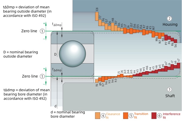
Shaft and Housing Tolerances Explained
To understand how to choose a fit, we must first look at the definitions. Shaft and housing tolerances are defined by international standards like ISO 286, which use an alphanumeric system to specify precision.
-
The Letter: Indicates the fundamental deviation (position of the tolerance zone).
-
Housing (Capital Letters): ‘H’ is the standard zero-line tolerance. ‘M’, ‘N’, ‘P’ indicate tighter fits.
-
Shaft (Lowercase Letters): ‘g’ or ‘f’ indicate clearance; ‘k’ or ‘m’ indicate transition; ‘p’ or ‘r’ indicate interference.
-
-
The Number: Denotes the tolerance grade (e.g., 6 or 7). Lower numbers mean tighter precision.
Quick Reference: Common Tolerance Table (50mm Diameter)
| Tolerance Pair | Fit Type | Typical Deviation (50mm dia.) | Best For |
|---|---|---|---|
| H7 / g6 | Clearance | Housing: 0/+0.025mm Shaft: -0.009/-0.025mm | Easy Assembly: Sliding fit, allowing parts to be moved or adjusted by hand. |
| H7 / k6 | Transition | Housing: 0/+0.025mm Shaft: +0.002/+0.018mm | Precision: Ideal for positioning; requires a light mallet tap for assembly. |
| H7 / m6 | Transition / Interference | Housing: 0/+0.025mm Shaft: +0.009/+0.025mm | General Machinery: Secures the bearing firmly under moderate loads; minimizes vibration. |
| H7 / p6 | Interference (Press) | Housing: 0/+0.025mm Shaft: +0.026/+0.042mm | Heavy Duty: Heavy loads or shock conditions; requires a press or thermal expansion to install. |
Rule of Fit Selection
Now that you know the codes, how do you decide between a clearance fit and an interference fit? It follows a strict engineering logic based on load direction and rotation. To prevent common failures like Bearing Creep, apply these standard rules:
Rotating Inner Ring (e.g., Electric Motors, Pumps)
The Scenario: The shaft rotates, and the load direction rotates with it.
The Rule: The inner ring must have an interference fit.
If the fit is too loose, the inner ring will slip on the shaft (“creep”), wearing down the metal and causing vibration.
-
Standard Loads: Use k5, m5, or m6.
-
Heavy/Shock Loads: Use tighter fits like n6 or p6.
Stationary Outer Ring (e.g., Standard Gearboxes)
The Scenario: The outer ring is stationary in the housing.
The Rule: A clearance fit (or sliding fit) is typically used for the housing.
This allows the bearing to “float” axially to accommodate thermal expansion and makes assembly/disassembly easier.
-
Recommended: H7, H8, or J7.
Rotating Outer Ring (e.g., Wheel Hubs, Conveyor Rollers)
The Scenario: The load rotates relative to the outer ring (or the housing rotates).
The Rule: The outer ring requires an interference fit in the housing to prevent it from spinning inside the bore.
-
Recommended: M7 or N7.
-
Heavy Shock Loads: Use P7.
The H7/m6 Industry Standard
If you look at the technical drawings for most general industrial equipment (like standard electric motors), you will almost always see the H7/m6 tolerance combination. Why is this specific pair so popular? It perfectly applies the “Golden Rules” mentioned above for the most common machinery setup (Rotating Shaft + Stationary Housing).
The Shaft: m6 (Transition to Interference)
The m6 tolerance class typically results in a very slight interference or a “snug” transition fit with standard bearing bores.
-
Why it works: It is tight enough to ensure the inner ring grips the shaft firmly and drives the rotation without slipping (addressing Rule #1), but not so tight that it eliminates the bearing’s internal clearance, which could cause overheating.
The Housing: H7 (Clearance/Sliding)
The H7 tolerance is the standard “hole basis” fit. Since standard bearing outer diameters often have a slight negative tolerance, an H7 hole typically results in a slide fit.
-
Why it works: It provides a predictable sliding fit. This is critical because bearings generate heat. As the shaft and inner ring heat up and expand, the “floating” outer ring in an H7 housing can slide slightly to relieve internal stress, preventing the bearing from seizing (addressing Rule #2).
Pro Tip: For high-precision applications, simply choosing H7/m6 isn’t enough. You must also consider the bearing’s accuracy class. (Read more in our Deep Groove Ball Bearing Accuracy Guide).
Factors to Consider When Choosing Bearing Fits
Selecting the right bearing fit isn’t one-size-fits-all; it depends on specific variables that are frequently overlooked. A standard H7/m6 might work for a motor, but put that same motor in a blast furnace or a vibrating screen, and it will fail.
Here are the critical factors that answer the question: “Why is my bearing overheating or vibrating?”
Load Magnitude and Nature
-
The Rule: The heavier the load, the tighter the interference fit must be.
-
Why: Heavy loads deform the inner ring, causing it to loosen on the shaft. Shock loads (vibration) require even tighter fits to prevent fretting corrosion. Conversely, light loads allow for looser fits to ease assembly.
Temperature Differences
-
The Rule: Fits change as parts heat up. You must account for the Temperature Gradient—the difference in temperature between the inner ring (usually hotter) and the outer ring.
-
The Risk: Since the inner ring gets hotter, it expands more than the outer ring. This tightens the fit during operation. If you start with a fit that is too tight, you risk eliminating the bearing’s internal clearance (C), leading to seizure.
-
Solution: In high-heat applications, don’t just loosen the shaft fit; consider using a bearing with C3 or C4 internal clearance to compensate for expansion.
-
Material Compatibility
-
The Rule: Watch out for mixing materials.
-
Scenario: A steel bearing on a steel shaft is straightforward. But putting a steel bearing into an Aluminum Housing?
-
The Risk: Aluminum expands nearly twice as fast as steel. As the housing heats up, the bore expands rapidly, potentially turning a tight interference fit into a loose clearance fit. You may need a much tighter initial fit (like P7) to compensate for this thermal growth.

Operating Speed (RPM)
-
The Rule: High speeds generally require tighter interference fits on the shaft.
-
Why: At high RPMs, centrifugal force tries to expand the inner ring outward, lifting it off the shaft. If the fit is too loose, the ring will spin on the shaft, causing immediate failure.
The Selection Checklist: 4 Steps to Success
To avoid the common pitfall of “forcing a fit,” follow this workflow before machining:
-
Evaluate the Load: Is it a standard fan (light load) or a rock crusher (heavy shock load)? Heavier loads need tighter fits (k→m→p).
-
Check the Temperature: Will the shaft be significantly hotter than the housing? If yes, ensure the bearing has enough internal clearance (C3).
-
Identify Materials: Are you placing Steel into Aluminum? Calculate the thermal expansion to ensure the fit stays tight at operating temperature.
-
Reference the Chart: Don’t guess. Use ISO 286 tolerance charts. Tool Tip: Use an Online Tolerance Calculator to simulate these scenarios and prevent math errors.
Don’t want to calculate this manually? Use our 2026 updated Tolerance Calculator below to get the exact values instantly.
Common Pitfall: A frequent user question is, “Why did my bearing seize immediately after installation?” This is often due to mounting damage. Forcing a tight interference fit (m6 or p6) without heating the bearing first can dent the raceways (Brinelling) or cause misalignment. Always use an induction heater for interference fits.
Step-by-Step Guide: How to Choose Shaft & Housing Tolerances (With H7/m6 Example)
Ready to apply this? Here’s a practical guide to selecting tolerances, using the industry-standard H7/m6 as an example—a go-to for many due to its balance of security and ease of assembly.
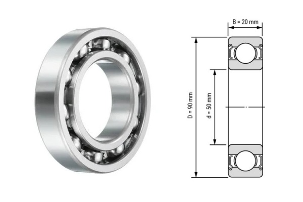
Determine Bearing Size & Load
Check your bearing’s catalog data for the ID (Inner Diameter) and OD (Outer Diameter).
-
Example: A standard 6210 ball bearing with a 50mm bore.
Assess Operating Conditions
Factor in load, speed, and temperature.
-
H7/m6 shines when: You have moderate loads, standard speeds (e.g., 500–3000 RPM), and the inner ring is rotating (e.g., electric motors).
Select Tolerances (Consult ISO Tables)
For a 50mm nominal diameter, the ISO 286 standard values are:
-
Housing (H7): 0 to +0.025mm (50.000 – 50.025mm). The hole is never smaller than the bearing.
-
Shaft (m6): +0.009 to +0.025mm (50.009 – 50.025mm). The shaft is always larger than the nominal size.
Verify the Fit (Do the Math)
Calculate the potential interference.
-
Since the bearing bore also has a tolerance (typically 0 to -0.012mm), an m6 shaft (+0.009) ensures a minimum interference of 0.009mm. This guarantees the ring won’t spin on the shaft, fulfilling the “Golden Rule.”
Measure with Precision
Skip the calipers. For bearing fits, accuracy to 0.001mm is crucial.
-
Tool: Use a calibrated Digital Micrometer for the shaft and a Bore Gauge for the housing. If the shaft measures 50.005mm (too small for m6), it could lead to slippage failure.
Install Properly
Never hammer a bearing directly.
-
For m6/p6 fits: The interference makes cold mounting difficult and risky. Use an Induction Heater to expand the inner ring for effortless installation, or use a hydraulic press for smaller sizes.
Is H7/m6 right for your CNC machine?
Yes, it is excellent for general drive shafts requiring stability.
-
Need higher precision? If your application requires minimal vibration (like a high-speed CNC spindle), consider switching the shaft tolerance to k6 (+0.002 to +0.018mm). k6 provides a “lighter” transition fit, reducing the stress on the bearing inner ring and preserving rotational accuracy.
4 Common Fit Selection Mistakes
Choosing the wrong tolerance is the root cause of many premature bearing failures. Here is what to avoid ensuring you don’t void your warranty:
Mistake 1: Choosing a Loose Fit for Easy Installation
It is tempting to choose a g6 or h6 shaft tolerance simply because it allows you to slide the bearing on by hand without tools.
-
The Risk: For a rotating shaft, this will lead to Inner Ring Creep. The ring will rotate relatively to the shaft, generating heat and producing “fretting corrosion” (reddish-brown powder). Over time, the bearing will cut a groove into the shaft, necessitating a costly shaft replacement.
Mistake 2: Excessive Interference (Thinking “Tighter is Better”)
Some engineers select p6 or r6 for standard applications, believing a tighter grip provides more security.
-
The Risk: A heavy interference fit expands the inner ring outward. If this expansion is too great, it eliminates the bearing’s Internal Clearance. The balls get crushed between the races, leading to rapid overheating and a high-pitched whining noise.
-
The Fix: If a tight fit is necessary for the load, you must use a bearing with C3 or C4 internal clearance to accommodate the expansion.
Mistake 3: Ignoring Housing Material (Aluminum vs. Steel)
Standard ISO tolerance charts assume steel shafts and steel housings.
-
The Risk: Aluminum expands nearly twice as much as steel when heated. An interference fit (like M7) in an aluminum housing at room temperature might turn into a loose clearance fit at 80°C (176°F). This allows the outer ring to spin in the housing (“spin out”), ruining the bore.
-
The Fix: For aluminum housings operating in heat, you often need a tighter fit (e.g., P7) or a steel insert liner.
Mistake 4: Overlooking Surface Finish (Roughness)
You measured the diameter correctly, but did you check the texture? If the shaft surface is too rough (poor turning), the measurement is misleading.
-
The Risk: The microscopic “peaks” of a rough surface will be flattened (smoothed out) during the first few hours of operation. This effectively reduces the interference, causing the fit to loosen over time.
-
The Rule: Always ensure the bearing seat is ground or fine-turned to a surface roughness of Ra 0.8 µm (N6) to Ra 1.6 µm. This ensures the fit stays tight for the long haul.
Conclusion
Selecting the right bearing fit is a balance between preventing creep (too loose) and preserving internal clearance (too tight). While H7/m6 is the reliable standard for most motors and pumps, always consider your specific load, speed, and material conditions.
Don’t let a simple tolerance error ruin your expensive machinery.
Need to check an H7/m6 bearing fit before ordering?
Send the bearing model, shaft diameter, housing bore, tolerance callouts, load direction, rotating ring, speed, temperature, housing material, internal clearance, lubrication method, and photos or drawings of the bearing seat. TFL can help compare available bearing options and confirm what information is needed before quotation.
FAQ
Q: What does H7/m6 mean in a bearing fit?
A: H7/m6 combines two tolerance decisions. H7 refers to the housing bore tolerance, while m6 refers to the shaft tolerance. It is commonly used when the inner ring rotates with the shaft and the outer ring is stationary in the housing.
Q: Is H7/m6 always the correct bearing fit?
A: No. H7/m6 is a common starting point, but it is not universal. The correct fit depends on rotating ring, load direction, bearing type, internal clearance, speed, temperature, housing material, and assembly method.
Q: When is m6 shaft tolerance used for bearings?
A: m6 shaft tolerance is often considered when the bearing inner ring rotates under load and needs a firmer shaft fit to reduce the risk of creep. The final shaft fit should still be checked against the bearing size, load, speed, and clearance.
Q: When should I avoid H7 housing tolerance?
A: Avoid assuming H7 is correct when the outer ring rotates relative to the load, the housing is hot or aluminum, the application has shock or vibration, or the bearing seat shows fretting or creep marks.
Q: What information helps TFL check an H7/m6 fit inquiry?
A: Send the bearing model, shaft diameter, housing bore, tolerance callouts, rotating ring, load direction, speed, temperature, housing material, internal clearance, lubrication method, and photos or drawings.